Seismic resistant retrofitting for buildings
Practical Action
The diagram above describes where cracks may first appear. Walls will experience different
modes of failure depending on their orientation to the earthquake movement. Parallel to the
ground movement, walls will experience shear and cracks will form in a diagonal fashion. The
cracks form an X-shape because shear will be experienced in both directions to follow the ground
movement. Diagonal cracks also form from the corners of openings since there stresses are highly
concentrated here. Vertical cracks are formed at the middle of walls perpendicular to the ground
movement, as this is the location of high bending stresses, as are ends where adjacent walls are
attached. Cracking here can lead to separation of the walls at corners. Cracks can propagate and
result in sections of the wall falling away and partially collapsing. In some instances, corners,
sections of wall or entire walls can fall out of plumb. Prolonged shaking can also lead to
delamination, in which a layer of masonry may fall away from the wall, or bulging, where the wall
face separates and creates an area of thick wall. Depending on the earthquake intensity and
duration, extensive damage can lead to total collapse. It is imperative that inhabitants are able to
escape before collapse happens.
Random Rubble Masonry
The predominant type of building in Bhuj, India is random rubble stone masonry. During the
2001 earthquake many walls made of random rubble failed, mostly due to separation of withes
and lack of interlock (Madabushi, 2005). The stones used are usually undressed (or uncut)
granite and units can vary in the amount of weathering they have been subjected to. This means
a variation in surface characteristics and hence a variation in the bonding with mortar. The
mortar itself could also be weak in some cases.
The use of ‘through stones’ ensure withes are interlocked with each other, preventing them from
falling away (delamination) or separating in sections (bulging). The placement of ‘through stones’
can be achieved on an existing wall by using reinforced concrete elements. This involves gently
removing stones to create a 75mm (3 inch) hole and inserting concrete reinforced with a hooked
bar the length of the wall thickness. The concrete is then cured for a minimum of 10 days. The
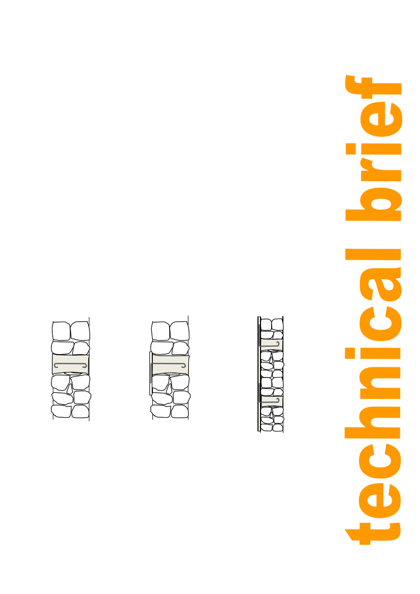
type of element can be varied depending on the type of bar used, depicted in the figures below.
(a) Stitching element:
stitches withes
together. Length is
50mm shorter than
wall width.
(b) Seismic belt shear
connector: anchors
seismic belt to wall.
Anchor is 150mm in
length.
(c) Vertical reinforcement
shear connector: anchors
vertical reinforcement.
Anchor is 400mm in length.
Figure 3: Variety of bond elements based on UNDP India (2007).
Note that the length of the bar should be 50mm shorter than the width of the wall, giving at
least 25mm of concrete cover either side. The reinforcement must be completely covered to
protect it from rust. The concrete should also be mixed with a polymer additive to prevent
shrinkage.
2